

.68uf cap value dropped to half in……
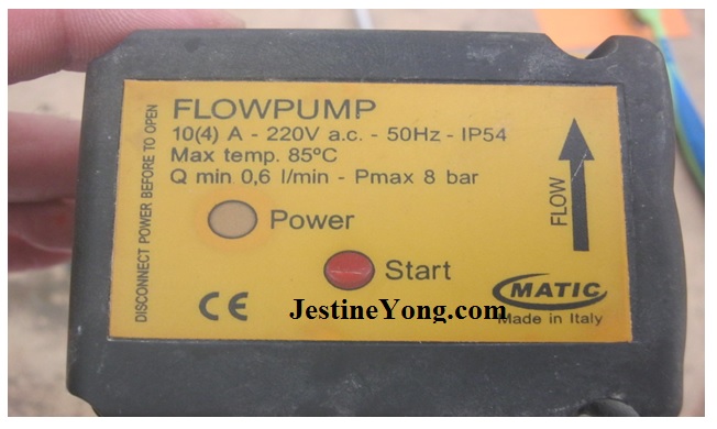
I got a call from a plumber about a water flow pump that was not working and he wanted me to go on location to check it out. He said it was completely dead and needed my attention. When we got there and checked the voltages going to the pump, I could read 220 volts reaching there but for some reason, it was not working.
I brought it back to the shop for more checking.
I have repaired such devices before so I know my way around it. When I took it apart, look what I found.
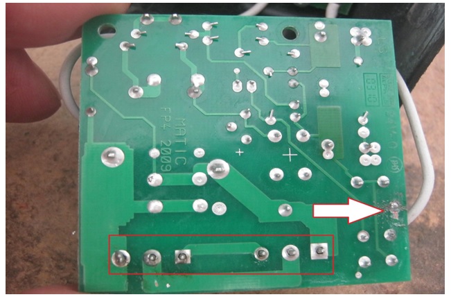
I saw some loose connection on the main power input and the output of the device. That explains why this pump was not working. I re soldered all the loose connection and I was ready for testing.
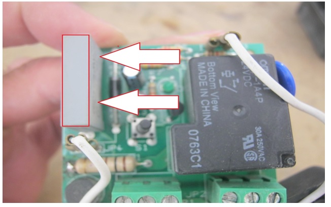
From experience, I know that these kinds of pumps a lot of time they fail because of the capacitor like the one you see in the photo.
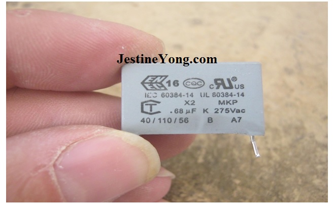
This is a .68 capacitor and it was reading way below that value so I had to replace that with a new one.
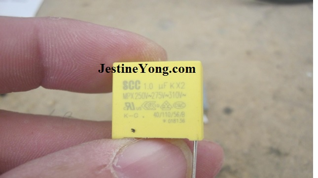
This is higher in value, 1UF and goes up to 250 volts.
I have tried it before and it works just fine.
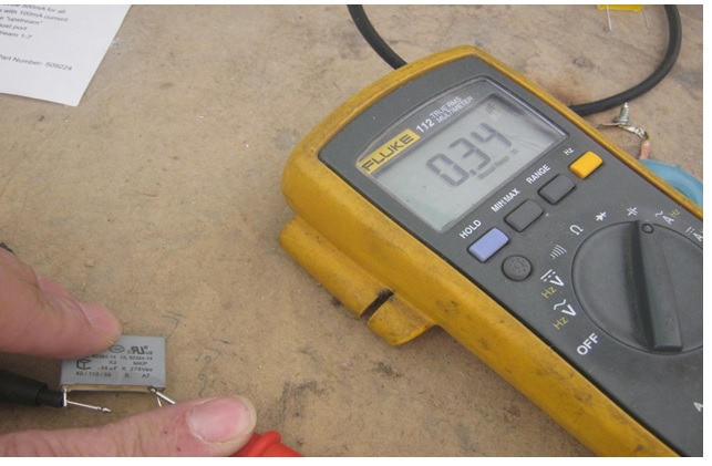
This is the value that I was getting when I tested the capacitor inside the pump.
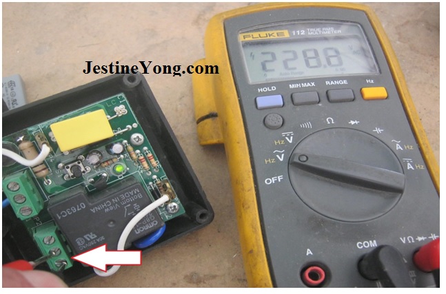
When testing the pump, the green light came one and I could read on the output pins 220 AC volts which is the right voltage for the motor to kick in.
Mission Accomplished.

This article was prepared for you by Waleed Rishmawi, one of our ‘Master Authors’ and currently working in the Bethlehem area of Palestine repairing electrical and electronic equipment.
P.S- Do you know of any your friends who would benefit from this content that you are reading now? If so, forward this website to your friends or you can invite your friends to subscribe to my newsletter for free in this Link.
Note: You can check his previous repair articles in the link below:
https://www.electronicsrepairfaq.com/main-bridge-rectifier-shorted
Sorry Waleed, but this capacitor replacement is wrong. First because the exact capacitance plays a crucial role for the health of the entire circuit (making things worse) and second because the application demands a X2 series capacitor working on 275 volts instead of an ordinary one of bigger capacitance but working in lower voltage than the minimum required (i.e. working marginally).
Paris: in the capacitance value went up from .68uf to 1uf and that only delays the motor one second to kick in which was totally fine after testing it now for more than a year. I have done it before you know.
our electricity will not exceed the 220 volts to that water flow pump which adding this will make it safe and enough.
yes, I understand your concern but in this case this method has been tested and so far none of the parts that got fixed came back for repair. have a blessed day
Another great example of the safety X2 capacitor used to replace a transformer. Where Xc of the capacitor in the formula 1/(2 x Pi x freq x C) gives the serieresistance that calculates the maximum current that the capacitor can give in that circuit that follows out 230Vac/Xc. The max current has gone up from 49 mA to 72.26mA by using a bigger capacitor with a lower Xc and it gives 23.26 mA more than when a 0.68 uF capacitor was used. But since you replaced these before it probably will be okay.
Albert: yes I understand your concern my friend and I understand what you are saying but I have done this before and so far none of the parts that got fixed this way came back for repair.
thanks for your input
Dear Waleed, I’m happy reading that you have no returns on these repairs.
Doing the math by myself, the original cap lets through 47mA, whereas the replacement lets 69mA to pass through the circuit.
Here i want to correct my previous comment. The resultant difference is of the order of nearly 147%. Not 210% as i miscalculated before.
Nevertheless this is also huge difference. The circuit must have an excellently chosen zener diode in terms of wattage to tolerate such a difference, as it is forced to absorb the excess current (supplied current minus the load current), plus these 22mA in other words, and dissipate it in form of heat.
Because of that, in the long run, the pcb will be cooked and the diode will inevitably burn (prematurely).
Apart from that, based on your writing only, without seeing the photo, i thought that the new cap was not of X2 series (although i don’t understand the three levels of voltage written on its body). The old one is marked to 275 volts which is the usual case.
Hopefully you understand my point of view on this repair.
My best regards!
Hello Albert
This is exactly the case here. It is a transformerless power supply. This perfectly explains why it couldn’t start with the original capacitor any longer. Because the current was not enough.
Now, since you did the math, the current is almost 210% in excess of the nominal value (and the capacitor’s rated voltage degraded!). The stabilizing zener diode is now forced to draw all the excess of the current in order to secure the operation of the circuit. It is therefore more than obvious that this zener will die way before its time comes. Hopefully, when this happens, it will stay shorted. Because if it opens…forget anything that follows after it…
Paris: with all due respect, how do you explain the part did not flow for the past year?
Waleed,
All I wanted to say (with all due respect as well) is that this is a modification, not a simple repair. Therefore, although it’s self evident and accepted as a method, it’s not properly documented. This is my point of view on it.
I use the similar “recipe” from time to time, when the original spare part cannot be found in the market.
Therefore I want to be crystal clear that am not criticising you about that repair. Our difference in thinking (this is all about) is that I would not let the result of my intervention (if I were in your shoes) to be a matter of statistics alone.
I just stand on a differend base. I would make my calculations first and then I would proceed accordingly.
Still there is a much easier approach to follow, especially when the same circuit comes many times to you for repairs, from different clients who bought it.
You have a very reliable multimeter as I see in the photos. You can measure the currents, before and after the repairs and then see, first for your own reassurance, if the resulting current (of the zener diode after the rectifier in this case) is within the specs and next to it have your readers fully convinced about the success of your repair, eliminating their need in putting questions on it.
Of course this process needs to be done the first time a new repair comes in and you suspect that many others like that one will follow. Then, for every one that follows, you can be sure about the result. The only practical difficulty is for that first time repair. The best is to find an original part. Otherwise you should either do the relevant math, or at least prove experimentally the fact,by relevant measurements, that the repair has being successfully done. Proved by proper documentation, therefore confirmed about its success.
Hopefully you understand my point of view and (upon this base) the reason that I answered indirectly the question you put to me.
Paris: I appreciate your input and explanations. have a blessed day
An expert and experienced solution applied! Many thanks for sharing! The comments of two experts are also worth in every word!
Parasuraman? yes, I understand these concerns I appreciate these comments but the the method is proven to work perfectly. I have repaired and tested many of these devices and none of them came back for repair.
have a blessed day my friend.
Waleed, I used such an X2 capacitor in my “https://jestineyong.com/diy-fully-automated-light-controlled-fan-regulator/” project which I designed and simulated in TINA. And that already works flawlessly since about the year 2012 (over about 7 years now)! So I know it most likely works!
Albert: thanks for sharing that. have a blessed day
Thank you very much for your dedication to electronic science
Cipriano: you are most welcome. have a blessed day